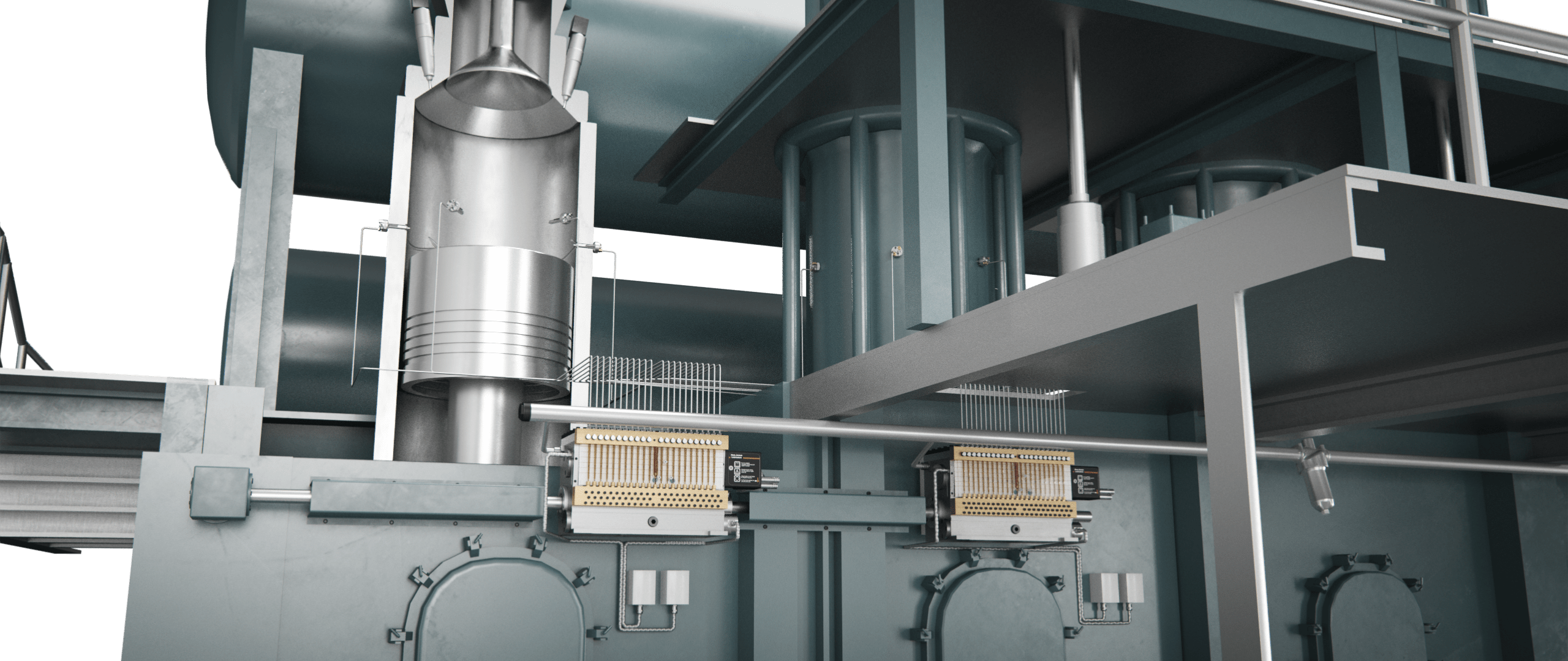
 HJL360
 HJ Mechanical
Please select a hotspot
to learn more.
 HJL360
 Please select a hotspot
to learn more.
The original design concept of the HJ Mechanical Cylinder Lubricators has proved to be stable and reliable and therefore the principle still applies today. The design, however, has been continuously improved to meet the customers’ increasing demands.
PLAY MOVIE Product folderLorem ipsum dolor sit amet, consectetur adipiscing elit, sed do eiusmod tempor incididunt ut labore et dolore magna aliqua
The adjusting bolts set the basic stroke lengths for each individual piston pump in the unit.
This allows the operator to manually change the amount of oil injected into the cylinder each engine revolution.
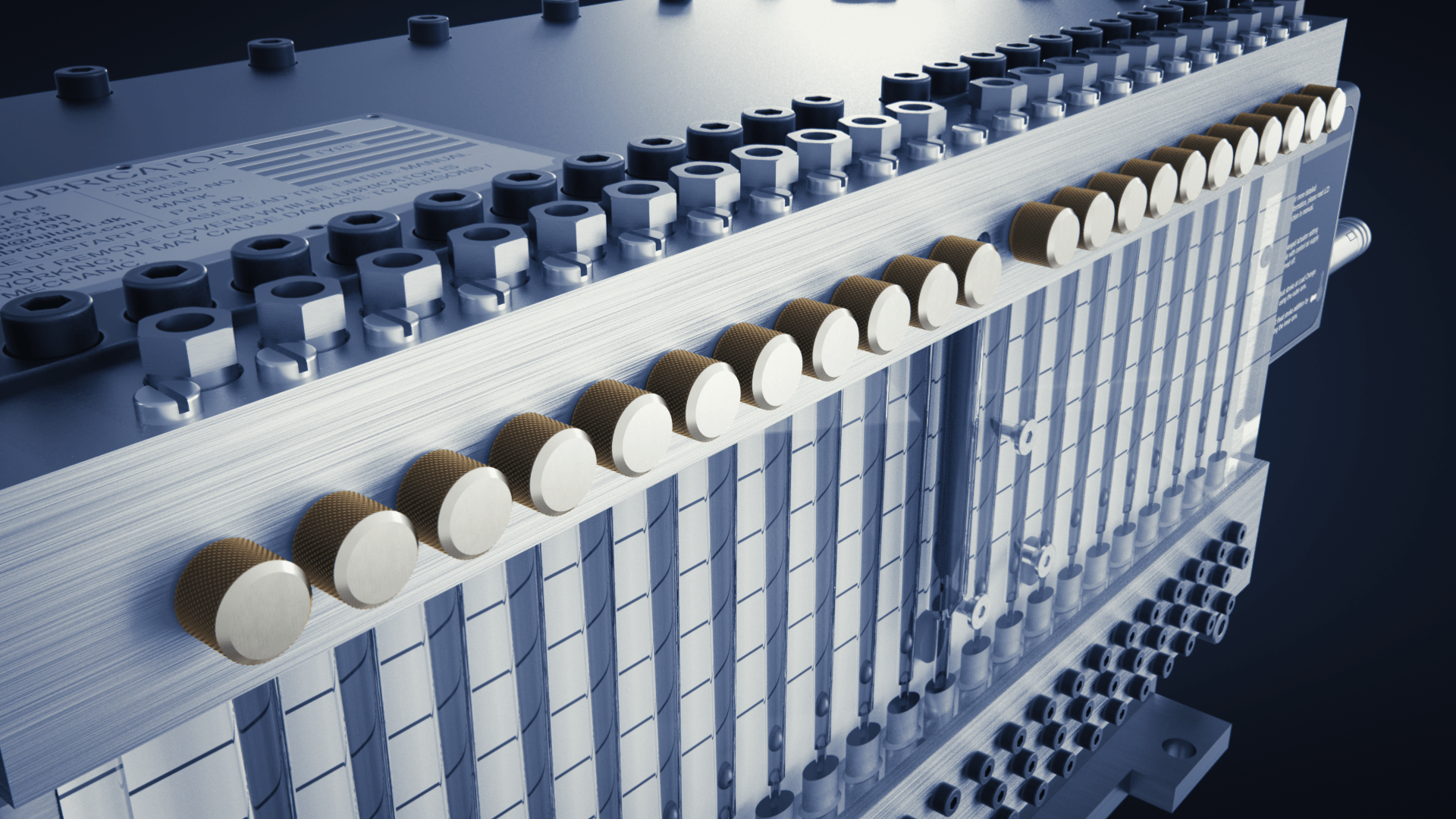
The LCD system receives signals from the governor or a control box connected to the fuel regulation shaft.
When load changes occur, e.g. during manoeuvring, these are registered by the LCD system which then provides extra lubrication for a short period of time.
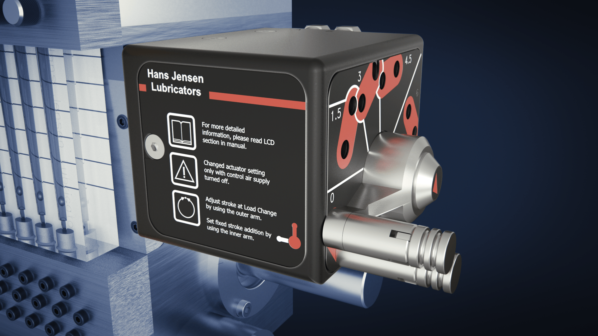
To confirm the function of each individual lube point the flow is visualised in the survey block by metal balls flowing up during pump activation. The level of the balls immediately after pump activation provides an indication of the cylinder oil quantity injected.
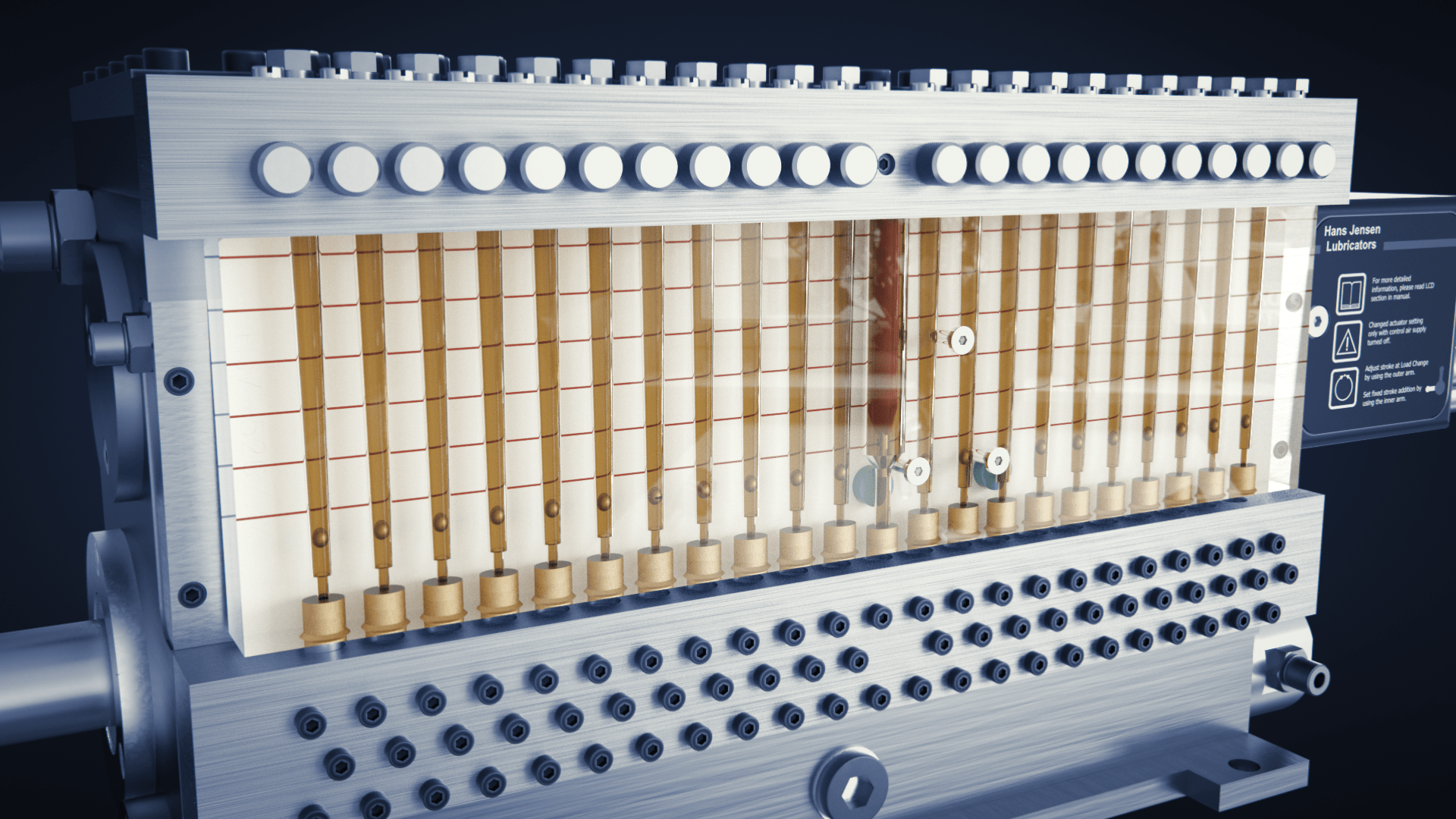
The camshaft operates synchronously with the fly wheel position and activates the piston pumps. Thereby the cylinder lube oil quantity is proportional to the engine speed, i.e. one piston stroke per revolution.
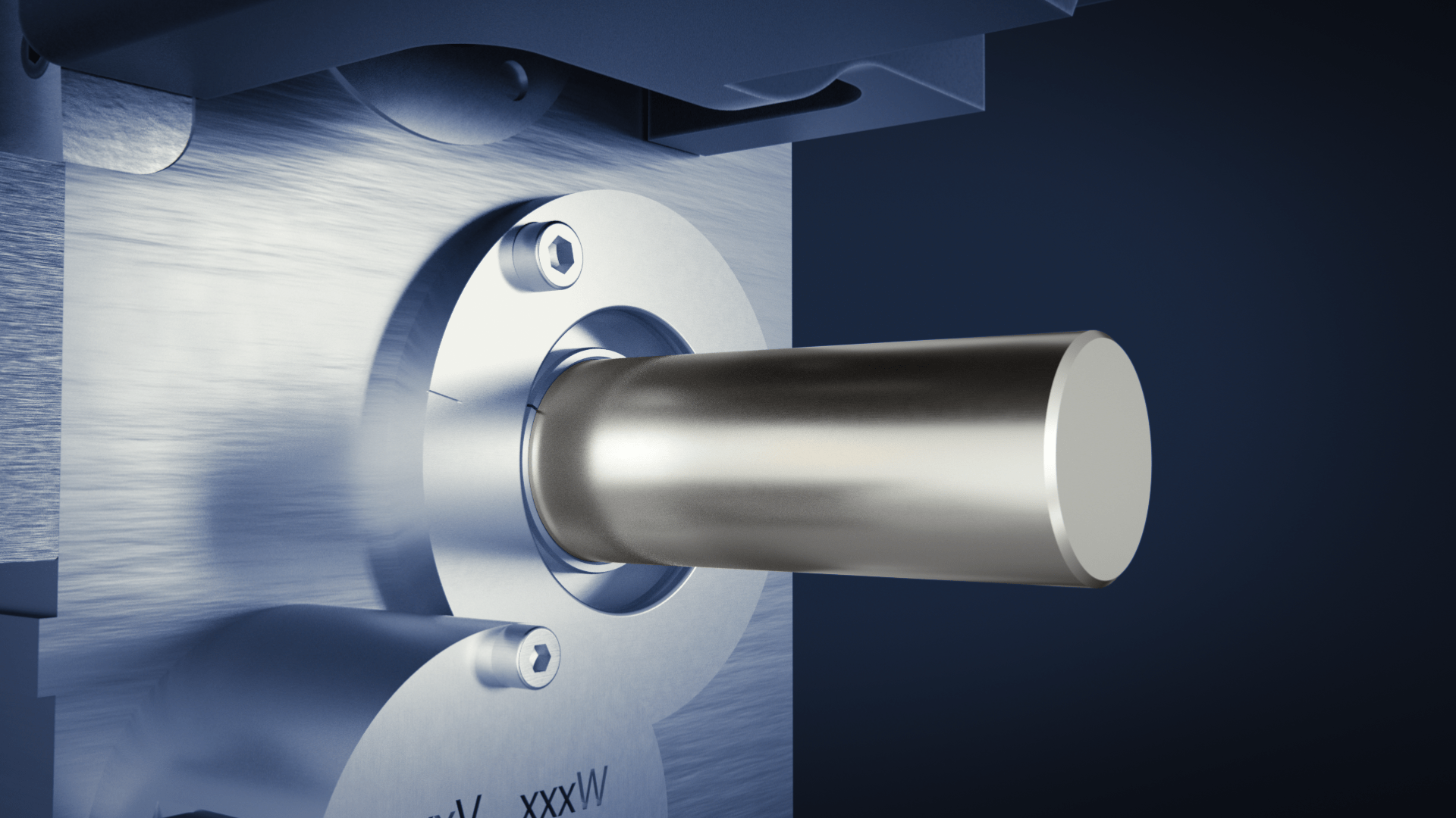
The HJ SIP ”Swirl Injection Principle” is a cylinder lube oil injection valve that sprays oil in tiny droplets utilizing the centrifugal power of the scavenging air swirl, ensuring optimum distribution of injected oil and thus an efficient use of the lube oil. HJ SIP works on all engine types and designs
Lorem ipsum dolor sit amet, consectetur adipiscing elit, sed do eiusmod tempor incididunt ut labore et dolore magna aliqua
The cylinder lube oil is sprayed into the cylinder through the nozzle opening. By spraying the lube oil in tiny droplets, into the scavenging air swirl a large surface area of the liner is covered to ensure optimal distribution of the cylinder oil. This in turn, ensures proper utilisation of the oil.
The nozzle opening is turned at an angle and injects the oil upwards onto the upper part of the cylinder liner where it is most needed, overlapping the next HJ SIP injection point.

Adjustment of closing pressure (35-60 bar) of the HJ SIP valve is done by an adjustable screw on top of the pressure plug. The adjustable screw is kept in place by a lock cover and a screw.

The drain pipe (T) is for the leak oil internally in the HJ SIP valve and is connected to the return pipe where the oil will be recirculated into the system.

The Pressure Pipe (P), is the oil inlet side of the HJ SIP valve.
The pressurized oil is pumped from the lubricator.
A strainer is mounted in the inlet of the HJ SIP valve at delivery. This must be removed after 500 running hours.

It looks like you are using an older version of iOS (below 11). This website might not work or display correctly. We recommend you use iOS version 11 and onwards. You may choose to proceed viewing the solution.
PROCEED